USB-A vs USB-C Charging: What OEM Buyers Need to Know
Your customers plug in a USB-A cable they have used for three years, and their new device takes six hours to charge. They switch to the USB-C cable that came in the box, and the same battery fills in 90 minutes. The charger itself did not change. The wall outlet did not change. What changed was the connector, the protocol, and the amount of power that could legally cross that interface.
If you are specifying charging architecture for a product line, this distinction is not a consumer convenience issue. It is a power electronics decision that affects your bill of materials, your thermal design, your certification path, and your customer satisfaction metrics.
This article breaks down the real engineering differences between USB-A and USB-C charging from a power-supply perspective. You will learn how the two standards differ in voltage negotiation, current capacity, protocol complexity, and thermal management, and you will know which connector to specify for your next product generation.
The Basics: Why the Connector Shape Is Not the Whole Story
USB-A and USB-C are often discussed as connector formats, but from a power electronics standpoint, they represent two fundamentally different approaches to delivering DC power from an adapter to a device.
USB-A is the rectangular connector that has been in service since 1996. It delivers 5V DC over four pins: VBUS, D-, D+, and GND. In its standard implementation, USB-A is limited to 500 mA (2.5W) from a computer port, or up to 2.4A (12W) from a dedicated charger using the BC 1.2 (Battery Charging) protocol. Some proprietary extensions push this further, but the physical connector and its four-pin architecture impose real limits on what can be negotiated across the interface.
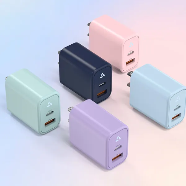
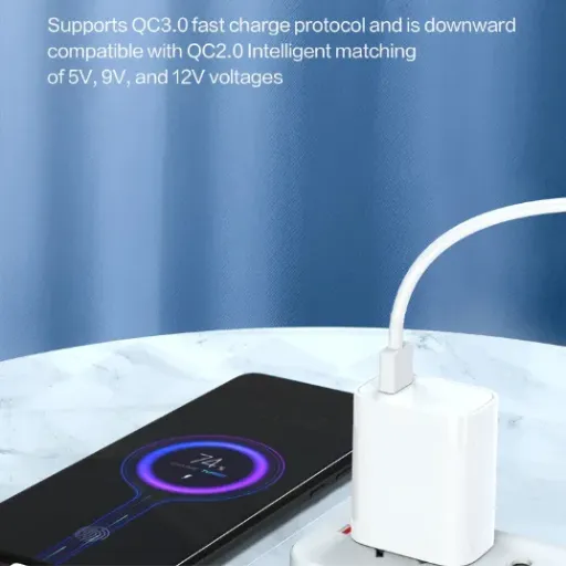
USB-C, introduced in 2014, uses a 24-pin reversible connector. Critically, it includes dedicated Configuration Channel (CC) pins that allow the device and the charger to communicate before power delivery begins. This communication enables USB Power Delivery (PD), a protocol that can negotiate voltage levels of 5V, 9V, 15V, and 20V, with current up to 5A, delivering up to 100W in standard PD and up to 240W under PD 3.1 with Extended Power Range (EPR).
Engineering note: The CC pins are what make USB-C a smart power interface rather than a dumb voltage rail. Without them, there is no negotiation, no voltage step-up, and no dynamic power management. This is why USB-A cannot natively support USB Power Delivery.
Physical pin count comparison
| Feature | USB-A | USB-C |
|---|---|---|
| Pins | 4 | 24 |
| Reversible | No | Yes |
| Power negotiation | None (fixed 5V) | Full bidirectional |
| Max standard power | 12W (BC 1.2) | 100W (PD 3.0) |
| Max extended power | 12W (proprietary only) | 240W (PD 3.1 EPR) |
| Data + power simultaneously | Yes | Yes |
| Orientation detection | No | Yes (via CC pins) |
For an OEM buyer, this means that choosing USB-C is not just a matter of selecting a newer connector. It is a decision to adopt a power negotiation architecture that changes how your device receives, manages, and dissipates energy.
Power Delivery: Watts, Volts, and What Your Device Actually Receives
The most important difference between USB-A and USB-C charging is what actually reaches your device's battery management system (BMS). A USB-A charger sends 5V. Period. The device can draw up to the current limit, but the voltage does not change.
USB-C with Power Delivery operates very differently. When a USB-C device is plugged in, the CC pins establish a connection. The device communicates its power requirements to the charger using the PD protocol. The charger then advertises its available power profiles. If both sides agree on a profile, the charger raises or lowers its output voltage accordingly, and current flows.
Standard USB Power Delivery voltage profiles
USB PD 3.0 defines fixed voltage levels that chargers and devices negotiate:
5V at 3A = 15W
9V at 3A = 27W
15V at 3A = 45W
20V at 3A = 60W
20V at 5A = 100W
Under PD 3.1 with Extended Power Range (EPR), additional profiles reach up to 48V at 5A (240W), though these require specific EPR-rated cables with active electronics.
What this means in practice: a USB-A charger tops out at 12W under standard protocols. A USB-C PD charger can deliver 20 times that power. For products with larger batteries, e-bikes, scooters, power tools, medical devices, this difference determines whether a full charge takes two hours or twenty.
Pro tip: When specifying a USB-C PD charger for your product, always define the specific PD profile your device requires. A 65W laptop charger and a 27W phone charger both use USB-C, but their internal designs, cost structures, and thermal envelopes are completely different.
Want to see how USB-C PD profiles map to your battery chemistry? Explore our LiFePO4 and Li-ion charger range to compare voltage and current configurations.
Protocol Complexity: What OEMs Must Design Around
USB-A charging is simple. The charger outputs 5V. The device draws current. The charger may use the D+ and D- data lines for basic handshaking under BC 1.2, but there is no dynamic voltage negotiation. The power path is essentially a fixed-voltage DC rail with a current limit.
USB-C Power Delivery introduces protocol complexity that must be managed on both sides of the cable.
The PD communication sequence
Attachment detection: The CC pins detect when a cable is connected and determine the cable orientation
Source capability advertisement: The charger sends its available power profiles over the CC line using BMC (Biphase Mark Coding)
Request: The device selects a profile and requests it
Accept/PS_RDY: The charger confirms the request and signals when the new voltage is stable
Power delivery: The negotiated voltage appears on VBUS
This sequence happens in milliseconds, but it requires a PD controller IC on both the charger side and the device side. For OEMs, this adds BOM cost, firmware development, and validation overhead.
USB-A protocol stack
No controller required on the charger side for basic 5V operation
BC 1.2 detection can be implemented with simple resistors on D+/D-
Fixed voltage simplifies the DC-DC converter design in the device
Lower certification complexity (no PD compliance testing)
USB-C PD protocol stack
Requires PD controller IC (e. g., Cypress CCG3, STMicro STUSB4500, Texas Instruments TPS65987)
Firmware must implement the PD state machine correctly
Device-side DC-DC converter must handle variable input voltage (5V–20V or higher)
Must pass USB-IF PD compliance testing for certification
Cable detection and E-mark reading for higher-current profiles
When Elena, a product manager at a Berlin-based e-bike startup, specified USB-C PD for her 48V battery pack's maintenance charger, she assumed the protocol would "just work." What she discovered during pre-production validation was that not all USB-C chargers advertise the same profiles. A 45W charger from one brand delivered 15V/3A, while a 45W charger from another delivered 20V/2.25A. Her device accepted both, but the internal buck converter ran 15% hotter at 20V, requiring a thermal redesign she had not budgeted for. The lesson: USB-C PD's flexibility is powerful, but it demands that you validate your device against the specific power profiles your customers are likely to encounter.
Thermal Management: More Power Means More Heat
Power is voltage multiplied by current. Heat is the waste product of that power conversion. When you move from USB-A's 12W maximum to USB-C PD's 100W or 240W, the thermal design of both the charger and the device must scale accordingly.
A USB-A charger delivering 5V at 2.4A handles 12W. Even at 80% efficiency, the internal losses are only 2.4W, easily dissipated through a small plastic enclosure without active cooling.
A USB-C PD charger delivering 20V at 5A handles 100W. At 92% efficiency (a realistic figure for a quality GaN-based design), internal losses are 8W. At 88% efficiency (more typical for lower-cost silicon designs), losses jump to 12W. That heat must go somewhere. It either raises the internal temperature of the charger, or it requires a larger enclosure, a heatsink, or an active fan.
Thermal implications for OEM product design
| Power Level | Typical Efficiency | Internal Loss | Thermal Strategy |
|---|---|---|---|
| 12W (USB-A max) | 85% | 1.8W | Passive, small enclosure |
| 27W (USB-C PD) | 90% | 3.0W | Passive, medium enclosure |
| 45W (USB-C PD) | 91% | 4.5W | Passive, larger enclosure or metal |
| 65W (USB-C PD) | 92% | 5.7W | Passive + heatsink, or small fan |
| 100W (USB-C PD) | 92% | 8.7W | Active cooling or large heatsink |
| 240W (PD 3.1 EPR) | 93% | 18W | Active cooling mandatory |
For OEM buyers, this thermal reality translates directly into product decisions. A 65W USB-C PD charger for a laptop replacement program costs more than a 12W USB-A charger not just because of the PD controller and larger power stage, but because the enclosure, thermal interface materials, and possibly the fan add cost and size.
Anenerge's USB-C PD adapter line uses GaN (gallium nitride) switching technology to push efficiency above 92% at 65W, which allows a 40% smaller enclosure than equivalent silicon-based designs. For OEM brand owners, that size reduction can be the difference between a charger that fits in a product's carrying case and one that does not.
Certification and Compliance: Different Paths for Different Connectors
The connector you choose affects the regulatory certifications your product needs, particularly for the charger itself.
USB-A chargers are straightforward from a compliance perspective. They are external power supplies (EPS) under DOE 10 CFR 430 and are subject to efficiency requirements (Level VI in the U. S., ErP Tier V in the EU). Safety certifications, UL 62368-1, CE, CB, apply to the adapter as a complete unit.
USB-C PD chargers carry those same requirements, plus additional compliance layers:
USB-IF certification: Required to use the USB-C logo. Involves interoperability testing at USB-IF authorized test centers.
PD compliance testing: The charger must correctly implement the PD protocol state machine, handle all required messages, and fail safely when connected to non-compliant devices.
Cable E-mark verification: For profiles above 3A, the charger must read the cable's E-marker chip to confirm the cable can handle the current. This adds firmware complexity.
Higher safety classification: A 100W charger operates at hazardous voltage and power levels, potentially requiring additional isolation testing and creepage distances compared to a 12W charger.
Regional compliance checklist by connector type
| Requirement | USB-A Charger | USB-C PD Charger |
|---|---|---|
| DOE Level VI (U. S.) | Yes | Yes |
| ErP Tier V (EU) | Yes | Yes |
| UL 62368-1 / CE / CB | Yes | Yes |
| USB-IF certification | No | Recommended for logo use |
| PD protocol compliance | N/A | Required for reliable operation |
| E-mark cable detection | N/A | Required for >3A profiles |
For OEM buyers planning multi-region launches, the certification stack for a USB-C PD charger is deeper and more expensive than for USB-A. Budget accordingly, and verify that your charger supplier holds current USB-IF certification with traceable test report numbers.
Anenerge ships USB-C PD adapters with full USB-IF certification, DOE Level VI efficiency, and the full safety certification stack. If you are entering markets that require both high power and documented compliance, download our certification package to verify which marks are current for your target regions.
Backward Compatibility: What Works With What
A common question from OEM buyers: "If I specify USB-C for my new product, will my customers still be able to use their old USB-A chargers?"
The answer depends on how you design your device.
USB-C is electrically backward compatible at the 5V level. A USB-C device that does not negotiate PD will receive 5V from any USB-C source, just as a USB-A device receives 5V. However, to use a USB-A charger with a USB-C device, the customer needs a USB-A-to-USB-C cable. This cable includes a 56 kΩ pull-up resistor on the CC line that tells the USB-C device it is connected to a legacy source, so the device limits its current draw to 500 mA or 900 mA (depending on implementation).
What this means in practice:
A USB-C phone plugged into a USB-A charger with an A-to-C cable will charge at ~5W. It will work, but slowly.
A USB-C laptop that requires 20V/3A (60W) will not charge at all from a USB-A charger. It may not even recognize the source as a valid power input.
A USB-C PD power bank that supports both input and output may charge from a USB-A source at reduced speed but output at full PD power to a connected device.
For OEMs, the backward compatibility question is really a customer-experience question. If your target market includes users with large inventories of USB-A chargers, you may want to include a USB-A-to-USB-C cable in the box, or you may want to accept that those users will have a degraded charging experience and design your customer support materials accordingly.
When the team at a Rotterdam-based scooter brand switched their fleet chargers from barrel-connector DC to USB-C PD, they assumed the universal availability of USB-C cables would reduce their support burden. What they found was that riders used whatever cable was handy, including cheap A-to-C cables from gas station counters. Those cables limited charge current to 500 mA, turning a 3-hour charge cycle into an 18-hour cycle. The brand eventually redesigned their charger dock with a captive USB-C cable to eliminate the variable.
When to Specify USB-A vs USB-C for Your Product
There is no universal right answer. The right connector depends on your product's power requirements, cost constraints, target market, and product lifecycle strategy.
Specify USB-A when:
Your device draws 10W or less (routers, small IoT sensors, basic LED controllers)
Cost is the dominant constraint and your BOM cannot absorb a PD controller
Your product targets price-sensitive markets where USB-A chargers are still the default
Your device does not benefit from faster charging (always-on appliances, backup systems)
You are refreshing a legacy product line and want to minimize design changes
Specify USB-C when:
Your device needs more than 15W (laptops, tablets, large battery packs, power tools)
Fast charging is a competitive feature (phones, e-bikes, portable power stations)
Your product roadmap includes bi-directional charging (power banks, dockable devices)
You are designing for a 5+ year lifecycle and want future-proofing
Your target market has largely transitioned to USB-C (most of Europe, North America, East Asia)
You need a single charger platform that covers multiple device categories
The single-source advantage
One argument for USB-C that OEM buyers often overlook is supply chain simplification. A 65W USB-C PD charger with interchangeable plugs can power a laptop, a tablet, a phone, and a portable monitor. A USB-A charger cannot. If your brand ships multiple product categories, specifying USB-C PD across the portfolio may reduce the number of SKUs you need to stock, qualify, and certify.
Anenerge's AC/DC power adapter platform includes both USB-A and USB-C PD configurations from 12W to 240W, with interchangeable regional plugs and the same certification stack. For brand owners managing multi-product charger programs, this lets you consolidate supplier relationships while covering every power level your devices require.
Efficiency and Sustainability: The Hidden Cost of the Wrong Choice
Energy efficiency standards apply to USB chargers regardless of connector type, but the efficiency implications of your choice run deeper than the certification mark on the label.
USB-A chargers are typically optimized for 5V output. Their efficiency curves peak at light to medium load, which matches the profile of small devices. A 12W USB-A charger powering a 5W IoT device may operate at 88–90% efficiency. The losses are small in absolute terms.
USB-C PD chargers must maintain efficiency across multiple voltage levels and a wide load range. A 65W PD charger that is efficient at 20V/3A (laptop charging) may be significantly less efficient at 5V/1A (phone trickle charging). The internal DC-DC conversion stages, the PD controller's quiescent current, and the overhead of the communication protocol all add losses at light load.
For OEMs with sustainability commitments or ENERGY STAR requirements, this means:
Specify the minimum PD profile your device actually needs. A device that only uses 9V/2A does not need a 100W charger.
Verify no-load power consumption. PD controllers add quiescent draw. A well-designed PD charger should still meet DOE Level VI no-load requirements (≤0.21W for adapters above 49W).
Consider active vs passive no-load. Some PD chargers enter a low-power state when no device is connected. Others keep the PD controller fully active. The difference can be 0.1W, small per unit, but measurable at scale.
At 15 million units per year, a 0.1W no-load difference represents 1.5 MW of continuous phantom load. That is not a marketing number. It is a real grid impact, and for brands reporting Scope 3 emissions or ENERGY STAR compliance, it is a line item.
Ready to specify the right USB-C PD charger for your product line? Request a free sample with your target voltage, current, and PD profile requirements, and our engineering team will return a proposal within 24 hours.
Key Takeaways for OEM Buyers
USB-A and USB-C are not simply old and new versions of the same thing. They are different power interfaces with different capabilities, different protocol requirements, different thermal envelopes, and different certification paths.
Here is what to remember when you specify charging for your next product:
USB-A tops out at 12W under standard protocols. It is simple, cheap, and sufficient for low-power devices, but it cannot deliver fast charging or variable voltage.
USB-C PD scales to 240W with negotiated voltage profiles from 5V to 48V. It enables fast charging, bi-directional power, and unified adapter strategies, but it adds BOM cost, protocol complexity, and certification depth.
Thermal design scales with power. A 100W charger is not just a bigger version of a 12W charger. It requires different magnetics, different semiconductors, and different thermal management.
Certification stacks are deeper for USB-C PD. Budget for USB-IF testing, PD compliance validation, and E-mark cable verification in addition to your standard safety and efficiency certifications.
Backward compatibility is partial. USB-C devices work with USB-A sources at reduced power, but high-power USB-C devices may not function at all on legacy 5V sources.
Efficiency at light load matters. A PD charger's efficiency across all voltage profiles and load conditions affects real-world energy consumption and your brand's sustainability metrics.
The connector you choose will be in your customer's hands for years. Choose the one that matches your device's power requirements, your market's expectations, and your product's lifecycle. Then specify a charger supplier that can deliver the certification stack, the efficiency, and the engineering support to make it work in production.
If you are evaluating USB-C PD chargers for your next product generation, the next step is straightforward. Send us your target PD profile, power requirements, and enclosure constraints. Our engineering team will return a proposed specification, efficiency curve, and sample timeline within 24 hours.
Recently Posted
-
Why Is My Fast Charger Not Charging Fast? 7 Technical Reasons Explained
June 8, 2026Last March, a product manager at a Rotterdam e-bike brand called us with a problem we see at least twice a quarter. Their new 48V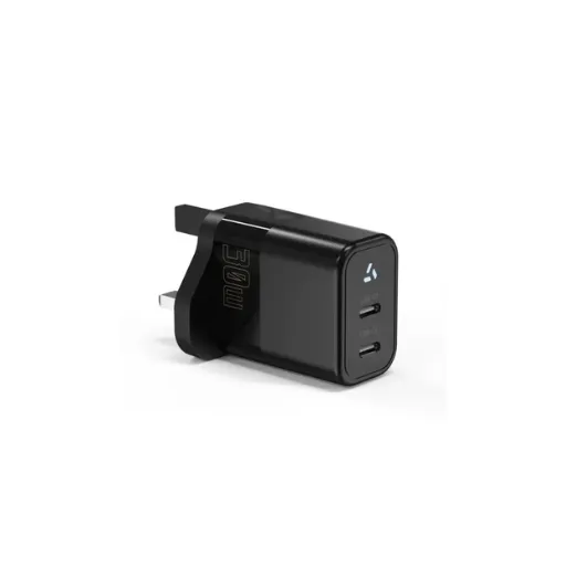 Read More
 -
What Makes a Fast Charger? A Technical Guide for OEM Buyers
June 8, 2026When the Rotterdam-based e-mobility brand VoltRide switched from 2A to 5A chargers on their 48V e-bike fleet in Q3 2024, customer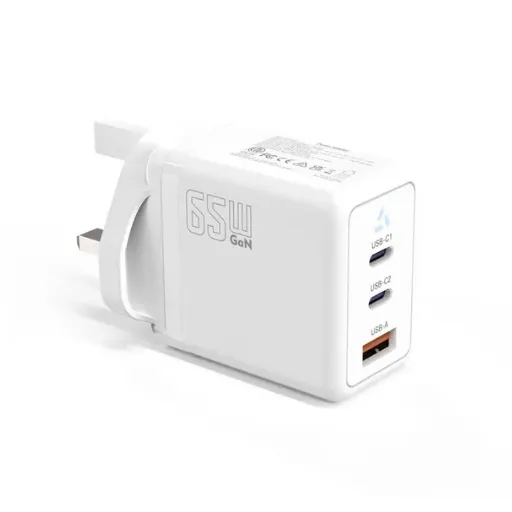 Read More
 -
QC3.0 vs QC4.0: What OEM Buyers Need to Know Before Specifying Fast Charging
June 6, 2026When Raj's team at a Bangalore-based smartphone accessories brand specified QC3.0 adapters for their 2024 power bank line, the Read More
 -
What Is a QC3 Plug? A Technical Guide for Adapter Buyers
June 6, 2026Marcus Chen's product team shipped 10,000 portable power stations to a U.S. distributor in March 2025. The units looked perfec Read More

Contact Us
Recommended Products
-
 65W USB-C GaN Wall Charger PD Fast Charging Adapter EU US Plug for Laptop Smartphone and TravelUS$ 6MOQ: 100 Pieces
 -
45W GaN USB-C Fast Charger JP Plug PD Wall Charging Adapter for IPhone MacBook and TabletsUS$ 8MOQ: 100 Pieces
-
QC3.0 30W USB Fast Charger With 18W Quick Charge Wall Adapter for Android and Mobile DevicesUS$ 4MOQ: 100 Pieces
-
Compact 18W Quick Charge 3.0 USB Charger 30W Fast Charging Adapter EU US Plug for TravelUS$ 2MOQ: 100 Pieces
-
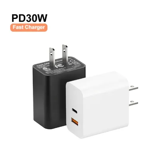
30W USB-C and USB-A PD Fast Charger Compact Wall Adapter for IPhone Samsung and IPadUS$ 3MOQ: 100 Pieces
-
35W Dual USB-C PD Charger Fast Charging Adapter for IPhone Samsung IPad and USB-C DevicesUS$ 3MOQ: 100 Pieces
-
65W USB-C GaN Charger EU Plug Fast Charging Adapter 65W USB-C PD Fast Charge Wall Charger Power Adapter for Macbook ProUS$ 5MOQ: 100 Pieces
-
65W GaN USB-C Fast Charger PD Wall Charging Adapter for Laptop IPhone and Mobile DevicesUS$ 5MOQ: 100 Pieces
-
100W GaN USB-C Fast Charger With PD 3.0 for Laptop, MacBook, IPhone & Multi-Device ChargingUS$ 12MOQ: 100 Pieces
-
45W GaN USB-C Fast Charger EU AU PD Fast Wall Charging Adapter for IPhone Tablets With CE REACH PassedUS$ 8MOQ: 100 Pieces
-
QC3.0 65W GaN USB C Super Fast Charger With UKCA 3 Ports PD 3.0 GaN Charger for Iphone Macbook SamsungUS$ 10MOQ: 100 Pieces
-
30W USB-C and USB-A GaN QC3.0 Fast Charging Adapter PD Fast Charger Compact Wall Adapter for IPhone Samsung and IPadUS$ 3MOQ: 100 Pieces
-
45W GaN USB-C Fast Charger With Dual Type-C and USB-A Ports PD Wall Charging AdapterUS$ 8MOQ: 100 Pieces
-
Dual USB C Ports QC3.0 30W Fast Charger With EU UK AU US USB-C PD Wall Chargeer 30W PD Power AdapterUS$ 3MOQ: 100 Pieces
-
Compact 65W GaN USB-C Wall Charger With Dual USB-C Ports and USB-A Fast Charging Adapter With CE UKCA ETL SAAUS$ 10MOQ: 100 Pieces
-
QC3.0 Fast Charging Adapter PD30W USB-C USB-A GaN PD Fast Charger PD 3.0 GaN Charger Compact Wall Adapter for IPhone Samsung and IPadUS$ 3MOQ: 100 Pieces
-
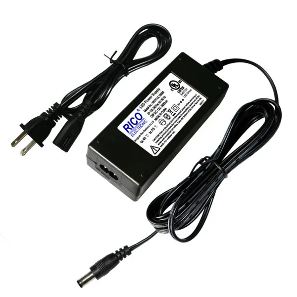
12V 5A 60W US EU AC DC Adapter LED Driver LED SMPS AC to DC Switching Power SupplyUS$ 5 - 7MOQ: 50 Pieces
-
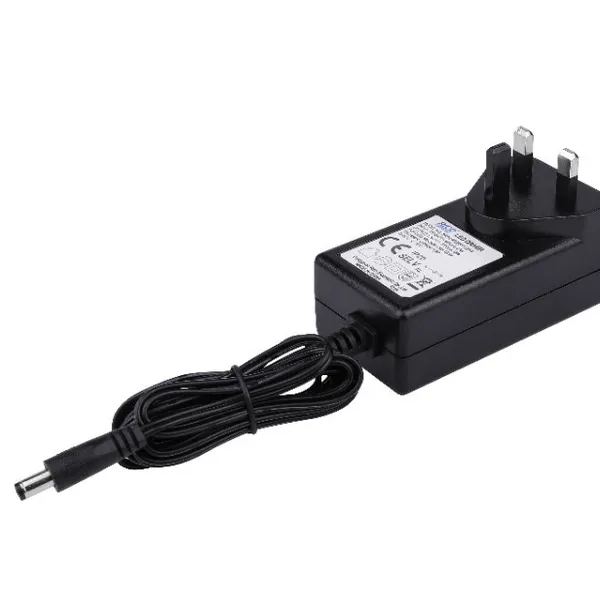
CE FCC CUL SAA KC PSE 24Vdc 48W Switching Power Supply AdaptersUS$ 5 - 7MOQ: 50 Pieces
-
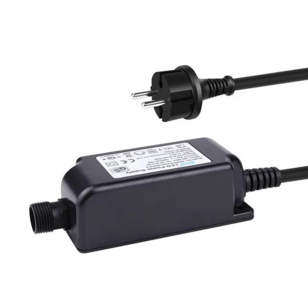
CE GS UKCA SAA CUL Qualified Waterproof Switching Power Supply Ip68 PSE UL SAA GS 12V 2AUS$ 3 - 6MOQ: 50 Pieces
-
12V 1A Factory OEM Waterproof AC Adapter for Laser Light Table Lamp ac dc Adaptor With TUV CE GS for EU MarketUS$ 5 - 7MOQ: 50 Pieces