How Does Fast Charging Work? An Engineer's Guide for OEM Buyers
When Chen, a power engineer at a Shenzhen e-mobility startup, first specced a fast charger for their 48V e-scooter, he assumed the answer was simple: buy a bigger power supply and push more amps into the pack. Six months later, his team had redesigned the enclosure twice, swapped the cable harness, and added an active cooling fan. The charger still throttled in summer.
Fast charging, he learned, is not a bigger version of slow charging. It is a coordinated system of higher power, smarter negotiation, and stricter thermal management.
This article explains how fast charging works from the power-supply level to the battery cell. You will learn the electrical math, the internal charger architecture, the communication protocols that enable higher power, and why the battery management system ultimately controls the speed. We will focus on what OEM buyers and procurement engineers need to specify, not just how the technology looks in marketing materials.
By the end, you will understand why a 100W USB-C charger, a 48V 5A e-bike charger, and a 240W industrial fast charger all follow the same physical rules, and why getting those rules right determines whether your product ships on time or returns under warranty.
Want to see a chemistry-matched fast charger built around your battery spec? Request a free engineering sample and we will return a proposed CC-CV profile within 24 hours.
The electrical foundation: watts = volts x amps
At the most basic level, fast charging means delivering more electrical power to a battery in the same or less time. Power is measured in watts, and watts are the product of voltage and current.
Power (W) = Voltage (V) x Current (A)
A 5V, 2A smartphone charger delivers 10W. A 20V, 5A USB Power Delivery charger delivers 100W. A 54.6V, 5A e-bike charger delivers 273W. If the battery can accept the higher power safely, it charges faster.
There are three ways a charger can increase power:
Raise voltage while keeping current the same
Raise current while keeping voltage the same
Raise both voltage and current together
Most modern fast charging systems use a combination. They negotiate a higher voltage with the device, which allows more power to flow through the same cable gauge without excessive heat. Then they increase current up to the safe limit of the cable, connector, and battery.
However, the charger cannot force power into the battery. The battery management system and the cell chemistry set the real limit. A 100W charger connected to a device that only accepts 18W will deliver 18W. A 5A e-bike charger connected to a BMS that limits current to 3A will deliver 3A.
The charger offers power. The device accepts what it can safely handle.
For OEM buyers, this is the first specification discipline: match charger capability to battery acceptance, not to marketing ambition.
Inside the charger: how AC becomes controlled DC
Before fast charging can happen, the charger has to convert AC wall power into tightly regulated DC. That conversion becomes harder as power increases, because every loss becomes heat, and heat limits how fast the system can run.
The AC input stage
The charger first rectifies AC mains voltage into rough DC. A power factor correction stage follows, which shapes the input current so the charger does not distort the grid. PFC is especially important at higher power levels, where regulatory limits on harmonic distortion become stricter.
The switching stage
A switching power supply chops the high-voltage DC at tens or hundreds of kilohertz. This high-frequency switching is what makes modern chargers small. A 50Hz transformer would be enormous; a 100kHz switching transformer can be tiny.
The switching stage is also where efficiency matters most. Every switching loss becomes heat, and at 240W or 273W, even 2% loss is enough to overheat a compact enclosure.
This is why gallium nitride has become popular in consumer fast chargers. GaN switches faster and with lower losses than silicon, so the charger produces less heat for the same output power. In industrial and e-mobility chargers, designers achieve similar results with larger heat sinks, fans, and more conservative switching frequencies.
The output regulation stage
After switching and isolation, the output stage regulates voltage and current precisely. A fast charger does not just output a fixed voltage. It adjusts voltage and current in real time based on what the battery needs during each phase of charging.
For lithium-based chemistries, that means following a CC-CV profile. The charger first holds current constant while voltage rises, then holds voltage constant while current tapers. A fast charger does not change this fundamental profile. It simply operates the CC phase at a higher current.
Engineering note: A lithium-ion battery charger and a LiFePO4 battery charger use different voltage cutoffs and current limits, but both follow CC-CV. The chemistry determines the parameters; the topology is the same.
How voltage and current are raised together
Raising voltage alone would deliver more power, but only up to the battery's voltage limit. Raising current alone would deliver more power, but only until the cable, connector, or cell resistance becomes the bottleneck. Fast charging standards solve this by negotiating both together.
Why higher voltage helps
Higher voltage means more power at the same current. A 5A current at 5V delivers 25W. The same 5A current at 20V delivers 100W. Because resistive losses in cables depend on current squared, keeping current lower while raising voltage reduces heat in the cable.
This is why USB Power Delivery uses voltage steps from 5V up to 48V. It is also why an e-bike charger can deliver 273W at 54.6V with a 5A cable, while a 12V system would need almost 23A to deliver the same power. The 23A cable would be thick, heavy, and hot.
Why current still matters
Eventually the device needs a specific voltage. You cannot charge a 3.7V lithium cell at 20V directly. The charger must step down to the cell's target voltage, and at that voltage, more current means more power.
For a 48V pack, moving from 2A to 5A increases power from 96W to 240W. The cable must handle that current without excessive voltage drop or heating.
Voltage drop is the hidden enemy
Every cable and connector has resistance. When current flows, some voltage is lost before it reaches the battery. A 48V 5A charger connected through a thin 2-meter cable might deliver only 46.5V at the pack.
The charger senses the lower voltage and either raises output or reduces current. If it cannot compensate enough, the effective charge rate drops.
This is why OEM cable specification matters as much as charger specification. A fast charger is only fast with the right cable and connector.
Inside the battery: what happens during fast charging
Batteries store energy through electrochemical reactions. Faster charging forces those reactions to happen faster, which creates physical stresses that do not appear at low current.
Ion movement and the SEI layer
During charging, lithium ions move from the cathode through the electrolyte and intercalate into the anode. At higher current, ions move faster. If they cannot insert into the anode quickly enough, they can plate as metallic lithium on the surface instead. This lithium plating thickens the solid electrolyte interphase layer and reduces capacity over time.
The SEI layer is a thin film that forms on the anode during the first cycles. It protects the anode but adds resistance. Fast charging thickens this layer faster, which increases internal resistance and reduces the energy the cell can deliver.
Heat generation
Not all electrical energy becomes stored chemical energy. Some becomes heat. The heat generated during charging depends on current squared times internal resistance. At 1C, a cell generates roughly four times the heat of a 0.5C charge.
That heat must go somewhere. If it builds up, cell temperature rises, degradation accelerates, and the BMS reduces current to protect the pack.
Temperature thresholds
Most lithium cells are designed to charge between 0°C and 45°C. Below 0°C, lithium plating risk rises sharply. Above 45°C, side reactions accelerate and cycle life drops. A good fast charging system monitors cell temperature and adjusts current accordingly.
This is why fast charging is not just about the charger. The battery chemistry, the pack thermal design, and the BMS all determine how much of the charger's offered power the pack can actually use.
Mini-story: In 2024, a scooter fleet operator in Jakarta deployed 1,200 vehicles with 1C fast chargers. The chargers were rated for tropical use, but the battery packs were sealed inside aluminum decks with no airflow. After six months, field data showed average charge temperatures of 52°C. Capacity fade doubled compared to the cell datasheet projection. The operator reduced charge current to 0.5C, added thermal pads to transfer heat to the deck, and saw charge temperatures drop to 41°C. Range degradation returned to expected levels. The fix was not a better charger. It was better thermal integration.
Communication protocols: the negotiation dance
Fast charging is not just electrical. It is also a conversation. The charger and the device must agree on voltage, current, and power before high-speed charging begins. If they do not agree, the system falls back to a safe, slower rate.
USB Power Delivery
USB PD is the most widely used standard for USB-C devices. It supports up to 240W and can negotiate voltage in steps: 5V, 9V, 15V, 20V, 28V, 36V, and 48V. The device tells the charger which voltage and current it can accept, and the charger adjusts accordingly.
Programmable Power Supply is an extension of USB PD that allows the device to request small voltage changes in 20mV or 40mV steps. This lets the device fine-tune voltage during the CV phase, reducing heat and improving efficiency.
Qualcomm Quick Charge
Quick Charge is common in smartphones and accessories. It uses the D+ and D- data lines to negotiate voltage steps. Newer versions add more granular control and better thermal management. For OEMs building third-party accessories, compatibility testing is essential because not all Quick Charge devices behave identically.
Proprietary protocols
Many brands use their own fast charging systems. OPPO VOOC, OnePlus Warp Charge, Xiaomi HyperCharge, and others often require matched chargers, cables, and devices. These systems can deliver very high power but lock the ecosystem. For OEM buyers, proprietary protocols mean licensing, certification, and supply chain complexity.
BMS communication in e-mobility
In e-bikes, scooters, and energy storage, the charger often communicates with the battery management system over CAN-bus, UART, or simple analog signaling. The BMS reports pack voltage, state of charge, temperature, and maximum allowed current. The charger uses this information to adjust output in real time.
Without this communication, the charger has to assume worst-case limits and charge more slowly. With good communication, the charger can push harder when conditions are safe and throttle when they are not.
CC-CV charging under speed pressure
The CC-CV profile does not disappear when charging gets faster. The charger still runs constant current first, then constant voltage. What changes is the current level during the CC phase and the thermal load during the CV phase.
The CC phase: where speed lives
Almost all the time savings of fast charging happen during the constant-current phase. A 20Ah pack charging at 0.2C takes 4A. At 1C, it takes 20A. The CC phase completes roughly five times faster at 1C.
However, higher current means more heat and more stress on the anode. The cell datasheet specifies a maximum charge C-rate, but maximum does not mean optimal for longevity. Many OEMs find that 0.3C to 0.5C offers the best balance between charge time and cycle life.
The CV phase: where heat accumulates
Once the pack reaches its cutoff voltage, the charger switches to constant voltage. Current tapers naturally as the pack fills. This phase cannot be rushed. Pushing more voltage to speed it up overcharges the cells and causes plating, gas generation, and capacity loss.
A fast charger may use voltage compensation and temperature monitoring to make the CV phase as efficient as possible, but it cannot eliminate the physics. The last 10-20% of charge always takes longer than the first 80%.
Termination current
The charger stops or switches to float when current drops below a threshold, typically 0.05C for LiFePO4. A charger that terminates correctly avoids holding the pack at high voltage indefinitely. Poor termination is a common cause of premature capacity fade in fast charging systems.
Learn more about CC-CV fundamentals in our CC-CV charging explained guide.
Thermal management: where the physics fight back
Every watt that does not go into the battery becomes heat. At fast charging power levels, that heat becomes the limiting factor. Thermal management separates reliable fast charging from warranty returns.
Heat in the charger
The charger itself generates heat in the rectifier, switching transistors, transformer, and output diodes. Higher efficiency means less heat. A 95% efficient 240W charger wastes 12W.
A 90% efficient charger wastes 24W. That difference of 12W is enough to change whether a fan is needed and whether the enclosure can be sealed.
For outdoor and industrial applications, sealed IP65 or IP67 enclosures make heat dissipation harder. Designers often use metal housings, thermal pads, and derating to keep internal temperatures under control.
Heat in the cable and connector
Connectors and cable contacts have resistance. At 5A or 10A, small contact resistances create significant heat. Poor-quality connectors can overheat, increase resistance further, and create a thermal runaway condition. This is why fast charging systems specify connector current ratings and require temperature-rated materials.
Heat in the battery
The battery is usually the largest heat source during fast charging. Internal resistance converts some charging power directly into heat. That heat must flow out of the cells, through the pack housing, and into the environment. If the path is blocked, cell temperature rises and the BMS throttles current.
Active and passive thermal control
Quality fast chargers use NTC thermistors to monitor pack temperature every few milliseconds. When temperature rises, the charger reduces current. In extreme cases, it pauses charging entirely. Some systems use active cooling fans or liquid cooling for very high power levels.
For OEMs specifying e-bike and scooter chargers, thermal design should be part of the product requirement, not an afterthought.
Ready to integrate a thermally validated fast charger into your product? Contact our engineering team to review your enclosure, cable, and battery layout.
System integration: why every link matters
Fast charging is a system performance, not a component performance. The charger, cable, connector, BMS, battery, and enclosure all have to work together. A weak link anywhere in the chain slows the whole system down.
| Component | What it contributes | What limits it |
|---|---|---|
| Charger | Converts AC to regulated DC; provides CC-CV profile | Power rating, efficiency, thermal design |
| Cable | Carries current from charger to battery | Gauge, length, temperature rating |
| Connector | Mechanical and electrical interface | Current rating, contact resistance |
| BMS | Monitors cell voltage, current, temperature | Current limit, protocol compatibility |
| Battery cells | Store energy and accept charge | Chemistry, C-rate, thermal path |
| Enclosure | Protects charger and manages heat | Material, airflow, IP rating |
This table explains why bench testing with a short lab cable can be misleading. In the field, the same charger may run slower because the cable is longer, the ambient temperature is higher, or the pack has aged and its internal resistance has increased.
Specification discipline for OEMs
Before placing a charger PO, define the full chain:
Charge time target based on real user needs, not marketing claims
Cell maximum C-rate from the cell vendor datasheet
Operating temperature range for the product's actual environment
Cable length, gauge, and connector that will ship with the product
BMS communication protocol if the charger needs to coordinate with the pack
Certifications for the target markets, including DOE Level VI where required
A charger specified in isolation will almost always disappoint in the field. A charger specified as part of a system will perform predictably.
Mini-story: A Los Angeles e-bike brand sourced a 48V 5A charger for their premium model. On the bench, the charger hit 5A and charged a 20Ah pack in about 4.5 hours. But customer reviews complained of 7-hour charge times. The QA team eventually tested the full assembly with the 1.8-meter cable and GX16 connector that shipped with the bike. Voltage drop across the cable and connector reduced effective current to 3.2A. The brand revised the cable gauge from 20AWG to 18AWG and shortened the harness to 1.2 meters. Charge times returned to the spec, and warranty claims dropped by 60%.
How Anenerge builds fast chargers as systems
At Anenerge, we do not treat fast chargers as isolated power supplies. Every OEM project starts with the battery spec, the charge time target, and the operating environment.
Our engineering team:
Reviews your cell datasheet and BMS requirements
Proposes a CC-CV profile with realistic C-rate and termination current
Sizes the charger, cable, and connector for continuous duty, not peak advertising
Provides thermal test data at your maximum ambient temperature
Builds samples within two weeks for validation
Produces with 100% functional and high-voltage isolation testing on every unit
We support custom voltage, current, connectors, labeling, and packaging through our OEM/ODM services. Our LiFePO4 chargers cover 12V to 72V outputs with current options from 2A to 20A, all designed for the thermal realities of real products.
Want to see how fast charging works with your specific pack? Request a free engineering sample and we will ship a unit matched to your battery chemistry within 7 days.
Conclusion
So how does fast charging work? It works by delivering more power to a battery in less time, using higher voltage, higher current, or both. The charger converts AC mains power into tightly regulated DC, negotiates voltage and current with the device or BMS, and follows a CC-CV profile at a higher current than a standard charger.
But the physics do not bend. More power means more heat. More heat means more stress on cells, cables, connectors, and enclosures. The battery management system and the cell chemistry set the real limit, not the charger label.
For OEM buyers, the key takeaways are:
Match charger power to what the battery can safely accept
Specify the full chain: cable, connector, BMS protocol, and thermal design
Demand continuous-load test data at real operating temperatures
Treat the charger as part of the battery protection system, not just a power source
Verify certifications for every target market before production
Fast charging is a powerful feature when it is engineered as a system. When it is treated as a marketing sticker on a bigger adapter, it becomes a warranty risk.
If you are designing an e-bike, scooter, energy storage system, or consumer electronics product that needs fast charging, the next step is clear. Send us your battery specification, charge time target, and operating environment. Our engineering team will propose a fast charging system that works in your product, not just on a datasheet.
Recently Posted
-
12V LiFePO4 Charger Buying Guide for OEM Brand Owners
June 22, 2026Last spring, a marine electronics brand in Florida shipped 2,000 portable power stations with "universal 12V chargers" b Read More
 -
48V LiFePO4 Charger Selection Guide for OEM Brand Owners
June 22, 2026When Elena received the first field failure report from her Rotterdam distributor in March 2024, the cause was not what she expect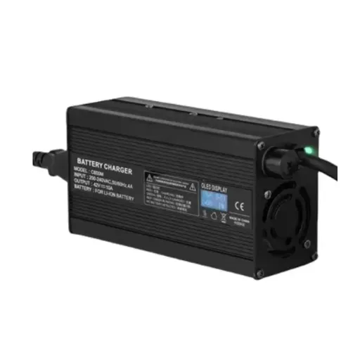 Read More
 -
LiFePO4 Battery Charger Selection Guide for OEM Brand Owners
June 22, 2026Marcus, a product manager at a Rotterdam-based e-bike brand, thought he had saved €12,000 on his first charger order. Six months l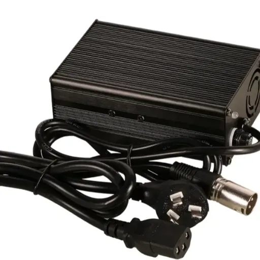 Read More
 -
Why Is My Phone Charging Slowly? Causes and Fixes
June 22, 2026At 7:45 a.m., Maya plugged her phone into the charger she grabbed from the hotel nightstand. By 8:30, the battery had climbed from Read More

Contact Us
Recommended Products
-
 65W USB-C GaN Wall Charger PD Fast Charging Adapter EU US Plug for Laptop Smartphone and TravelUS$ 6MOQ: 100 Pieces
 -
45W GaN USB-C Fast Charger JP Plug PD Wall Charging Adapter for IPhone MacBook and TabletsUS$ 8MOQ: 100 Pieces
-
QC3.0 30W USB Fast Charger With 18W Quick Charge Wall Adapter for Android and Mobile DevicesUS$ 4MOQ: 100 Pieces
-
Compact 18W Quick Charge 3.0 USB Charger 30W Fast Charging Adapter EU US Plug for TravelUS$ 2MOQ: 100 Pieces
-
30W USB-C and USB-A PD Fast Charger Compact Wall Adapter for IPhone Samsung and IPadUS$ 3MOQ: 100 Pieces
-
35W Dual USB-C PD Charger Fast Charging Adapter for IPhone Samsung IPad and USB-C DevicesUS$ 3MOQ: 100 Pieces
-
65W USB-C GaN Charger EU Plug Fast Charging Adapter 65W USB-C PD Fast Charge Wall Charger Power Adapter for Macbook ProUS$ 5MOQ: 100 Pieces
-
65W GaN USB-C Fast Charger PD Wall Charging Adapter for Laptop IPhone and Mobile DevicesUS$ 5MOQ: 100 Pieces
-
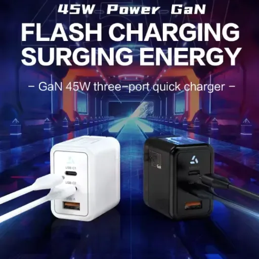
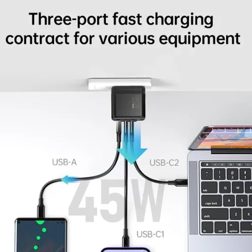
100W GaN USB-C Fast Charger With PD 3.0 for Laptop, MacBook, IPhone & Multi-Device ChargingUS$ 12MOQ: 100 Pieces
-
45W GaN USB-C Fast Charger EU AU PD Fast Wall Charging Adapter for IPhone Tablets With CE REACH PassedUS$ 8MOQ: 100 Pieces
-
QC3.0 65W GaN USB C Super Fast Charger With UKCA 3 Ports PD 3.0 GaN Charger for Iphone Macbook SamsungUS$ 10MOQ: 100 Pieces
-
30W USB-C and USB-A GaN QC3.0 Fast Charging Adapter PD Fast Charger Compact Wall Adapter for IPhone Samsung and IPadUS$ 3MOQ: 100 Pieces
-
45W GaN USB-C Fast Charger With Dual Type-C and USB-A Ports PD Wall Charging AdapterUS$ 8MOQ: 100 Pieces
-
Dual USB C Ports QC3.0 30W Fast Charger With EU UK AU US USB-C PD Wall Chargeer 30W PD Power AdapterUS$ 3MOQ: 100 Pieces
-
Compact 65W GaN USB-C Wall Charger With Dual USB-C Ports and USB-A Fast Charging Adapter With CE UKCA ETL SAAUS$ 10MOQ: 100 Pieces
-
QC3.0 Fast Charging Adapter PD30W USB-C USB-A GaN PD Fast Charger PD 3.0 GaN Charger Compact Wall Adapter for IPhone Samsung and IPadUS$ 3MOQ: 100 Pieces
-
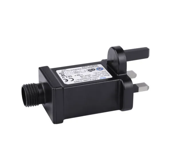
12V 5A 60W US EU AC DC Adapter LED Driver LED SMPS AC to DC Switching Power SupplyUS$ 5 - 7MOQ: 50 Pieces
-
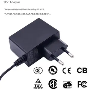
CE FCC CUL SAA KC PSE 24Vdc 48W Switching Power Supply AdaptersUS$ 5 - 7MOQ: 50 Pieces
-
CE GS UKCA SAA CUL Qualified Waterproof Switching Power Supply Ip68 PSE UL SAA GS 12V 2AUS$ 3 - 6MOQ: 50 Pieces
-
12V 1A Factory OEM Waterproof AC Adapter for Laser Light Table Lamp ac dc Adaptor With TUV CE GS for EU MarketUS$ 5 - 7MOQ: 50 Pieces