Is PD Charging Safe? What OEM Buyers Need to Know About USB Power Delivery
In March 2024, a consumer electronics brand in Los Angeles recalled 12,000 USB-C power adapters after field reports of overheating during fast-charge cycles. The root cause was not the USB Power Delivery protocol itself. It was a poorly implemented PD controller that failed to negotiate voltage steps correctly, pushing 20V into a device designed for 9V. The incident cost the brand $340,000 in direct losses and a damaged reputation it is still rebuilding.
If you are specifying chargers or adapters for a product line, that story matters. USB Power Delivery (PD) is everywhere now, from smartphones and laptops to routers and IoT gateways. Your end customers are asking whether PD charging is safe. The answer is yes, when the adapter is engineered, certified, and manufactured correctly. The answer is no, when corners are cut on the PD controller, the power stage, or the safety certifications.
This article explains how USB Power Delivery actually works, what safety mechanisms are built into the protocol, and the five things every OEM buyer must verify before sourcing a PD adapter or charger. It draws on our experience manufacturing USB-C PD adapters for brands shipping to North America, Europe, and Southeast Asia.
How USB Power Delivery actually works
USB Power Delivery is a protocol, not just a higher wattage. It allows a charger and a device to communicate over the CC (configuration channel) lines of a USB-C cable and negotiate the optimal voltage and current for charging. This negotiation happens before any significant power flows.
Here is the sequence in plain terms:
Source capability advertisement: The charger broadcasts the power profiles it supports, typically 5V, 9V, 12V, 15V, and 20V at various current levels
Request: The device reads those profiles and requests the one that matches its battery and charging circuit
Acceptance: The charger confirms it can deliver the requested profile
Power delivery: The charger steps to the negotiated voltage, and current flows
Ongoing monitoring: The charger and device continue communicating; if either side reports a fault, the charger drops back to 5V or disconnects entirely
This handshake is the reason PD charging is fundamentally safer than older "dumb" fast-charging schemes. A legacy 2A USB-A charger simply pushes 5V and hopes the device limits its own current. A PD charger waits for permission, confirms capability, and monitors continuously.
The voltage and power tiers
PD 3.1 (the current specification) supports power levels up to 240W using Extended Power Range (EPR). Most consumer electronics use Standard Power Range (SPR), which tops out at 100W. The common voltage steps are:
| Voltage | Max Current (SPR) | Max Power | Typical Applications |
|---|---|---|---|
| 5V | 3A | 15W | Small IoT devices, basic charging |
| 9V | 3A | 27W | Smartphones, tablets, small appliances |
| 12V | 3A | 36W | Tablets, monitors, small laptops |
| 15V | 3A | 45W | Laptops, larger tablets |
| 20V | 5A | 100W | Laptops, workstations, high-power devices |
The key point for OEM buyers: your device only receives the voltage it requests. A 9V smartphone connected to a 100W PD charger still charges at 9V, because the PD protocol enforces that agreement.
Built-in safety mechanisms of the PD protocol
USB Power Delivery includes multiple layers of protection that operate independently of the adapter manufacturer. Understanding these helps you explain PD charging safety to your customers and your QA team.
Hardware-level protections
Every PD adapter must include these protection circuits to pass IEC 62368-1 and UL safety testing:
Over-voltage protection (OVP): If the output voltage exceeds the negotiated level by more than a defined margin, the adapter shuts down
Over-current protection (OCP): If the device tries to draw more current than agreed, the adapter limits or cuts output
Over-temperature protection (OTP): Internal temperature sensors shut the adapter down before thermal damage occurs
Short-circuit protection (SCP): A direct short across the output triggers immediate shutdown
Isolation: 3KVAC or higher isolation between the AC mains side and the DC output side prevents electric shock
These protections are not optional features you add at a premium. They are baseline requirements for any adapter that carries UL, CE, or CCC marks.
Protocol-level safety
Beyond hardware, the PD protocol itself includes safety checks:
Cable current rating detection: The charger reads the cable's e-marker chip to verify it can handle the requested current. A 3A cable cannot be used for 5A charging
Voltage step validation: Before stepping to a higher voltage, the charger confirms the device is ready and the cable supports it
Hard reset capability: Either side can issue a hard reset at any time, forcing the link back to 5V and zero current
Timer-based failsafes: If communication stops, the charger reverts to 5V within a defined timeout
Pro tip: When evaluating PD adapter suppliers, ask for the fault-response test report. A reputable manufacturer will document exactly how the adapter responds to each protection trigger, with oscilloscope captures showing the voltage and current waveforms.
What makes PD charging unsafe (and how to avoid it)
If the protocol is safe by design, why do PD chargers still fail in the field? The answer is almost always in the implementation, not the specification. Here are the four most common failure modes we see in returned adapters and competitor teardowns.
1. Counterfeit or substandard PD controllers
The PD controller IC is the brain of the adapter. It handles the protocol negotiation, voltage step requests, and fault monitoring. Quality controllers from vendors like Cypress (Infineon), Richtek, or ON Semiconductor cost more but include full protocol validation and robust fault handling.
Cheaper knockoff controllers may implement only the basic PD messages and skip the safety checks. In our lab, we have tested adapters that accepted a 20V request from a device that only rated for 9V, because the controller did not validate the request against the device's capabilities.
What to verify: Ask your supplier which PD controller IC they use. Cross-reference it against the USB-IF certified product list. If the supplier cannot name the IC manufacturer, that is a red flag.
2. Inadequate thermal design
A 65W PD adapter in a compact enclosure generates significant heat. At 92% efficiency, that still means 5.7W of heat to dissipate. If the enclosure is too small, the thermal path is poorly designed, or the switching frequency is pushed too high to save on magnetics size, the adapter runs hot.
When Marcus, a product manager at a smart-home brand in Rotterdam, sourced PD adapters for a new line of connected lighting controllers, he chose the smallest enclosure he could find. The adapters looked great on the shelf, but after three hours of continuous 45W operation in a closed cabinet, internal temperatures hit 85 degrees Celsius. The OTP circuits triggered, the lights flickered off, and customer complaints flooded in. Switching to an adapter with a proper aluminum heat sink and larger ventilation area solved the issue, but the SKU change cost him six weeks and a distributor contract.
What to verify: Request thermal test data at full load and at elevated ambient temperature. For enclosed or recessed installations, demand testing at 40 degrees Celsius ambient or higher.
3. Missing or fake certifications
PD adapters operate at up to 20V (or 48V under EPR), which is hazardous voltage. Every market requires safety certification:
U. S.: UL 62368-1 (or UL 60950-1 for older designs)
EU: CE marked to EN 62368-1
UK: UKCA marked (same standard as CE post-Brexit)
Australia: SAA / RCM
Global: CB Scheme certificate
Fake certifications are common in the marketplace adapter segment. We have seen adapters with printed UL logos and no actual listing. Always verify certification numbers on the issuing body's database.
Want to see how certification verification fits into your full sourcing checklist? Our DOE Level VI compliance guide covers the same verification process for efficiency certifications. The principle is identical: trust the test report, not the label claim.
4. Poor cable quality or compatibility
The cable is part of the safety system. A 100W PD charge requires a cable with an e-marker chip that tells the charger "I can handle 5A." Cheap cables omit the e-marker, use undersized wire, or have weak connectors that overheat under sustained load.
The USB-IF runs a certification program for cables, but non-certified cables flood the market. If your product ships with a cable, the cable quality reflects on your brand, not the cable maker.
Certifications that prove PD adapter safety
When you are sourcing PD adapters for your product line, certifications are your objective proof of safety. Here is what each mark actually means for PD charging.
| Certification | What It Covers | Relevance to PD Safety |
|---|---|---|
| UL 62368-1 | U. S. safety standard for audio/video and IT equipment | Validates OVP, OCP, OTP, SCP, and isolation requirements |
| CE / EN 62368-1 | European safety standard | Same testing scope as UL 62368-1 for EU market entry |
| UKCA | UK post-Brexit safety marking | Confirms compliance with UK-adopted EN standards |
| CB Scheme | International mutual recognition | Simplifies national certification in 50+ member countries |
| FCC Part 15 | U. S. electromagnetic interference | Ensures PD switching noise does not disrupt nearby electronics |
| DOE Level VI | U. S. energy efficiency | Verifies active-mode efficiency and no-load power draw |
| USB-IF PD Certification | Protocol compliance | Confirms the adapter implements PD messaging correctly |
The USB-IF certification is particularly important for PD adapters. It tests protocol behavior, not just electrical safety. An adapter can pass UL and still fail USB-IF if it handles PD messages incorrectly.
At Anenerge, every USB-C PD adapter we ship carries the full certification stack for the target market, including USB-IF PD certification where required. We provide current test reports with traceable report numbers for every production batch.
Specifying safe PD adapters for your product line
If you are an OEM buyer or product manager adding USB-C PD charging to your product, here is the specification checklist our engineering team recommends.
1. Match the PD profile to your device's input
Your device's charging circuit defines what it can accept. Do not assume higher wattage is better. A device with a 9V / 2A input will charge at 18W whether you pair it with an 18W adapter or a 100W adapter. The extra capability in the 100W adapter adds cost and size with no benefit.
Common PD profile selections:
Smartphones and small IoT: 5V / 3A (15W) or 9V / 2A (18W)
Tablets and small displays: 9V / 3A (27W) or 12V / 2.25A (27W)
Laptops and workstations: 15V / 3A (45W), 20V / 3.25A (65W), or 20V / 5A (100W)
High-power or future-proofed: 20V / 5A (100W SPR) or EPR up to 240W
2. Define the operating environment
Where will the adapter live? A wall-mounted router adapter in a climate-controlled office has different thermal needs than an outdoor security camera adapter in Dubai summer. Specify:
Ambient temperature range
Ventilation (open air, enclosure, recessed)
Duty cycle (continuous, intermittent, standby-heavy)
Ingress protection (IP rating for outdoor or industrial use)
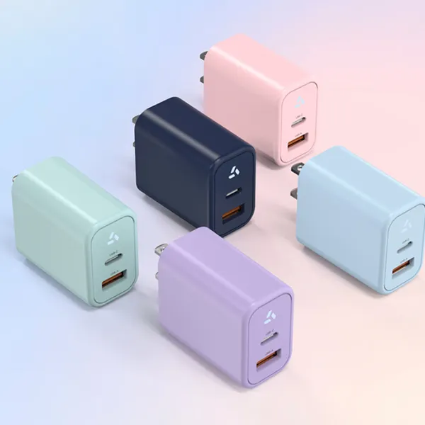
3. Choose the right enclosure and connector
PD adapters come in several form factors:
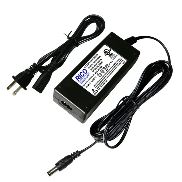
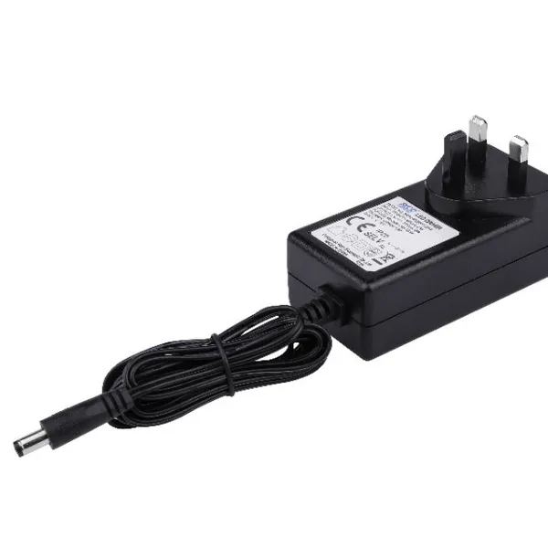
Wall-mount (plug-in): Compact, no external AC cord, good for travel chargers and small devices
Desktop (external AC cord): Larger, better heat dissipation, easier to position
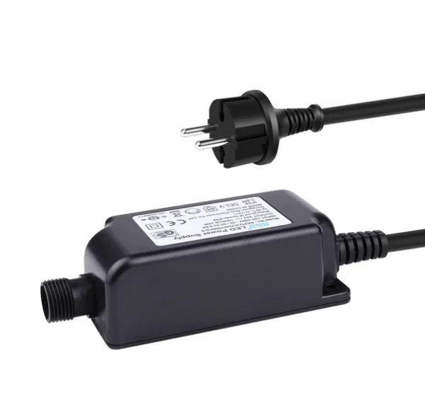
Waterproof / outdoor: Sealed enclosures with IP65 or IP67 ratings for field installation
The connector is equally important. USB-C is standard for PD, but the cable length, jacket material, and strain relief all affect field reliability.
Ready to move from specification to sample? Send us your device input requirements, target PD profile, and operating environment. Our engineering team will propose a certified adapter design and ship an engineering sample within two weeks.
4. Verify the full certification stack
Do not settle for "CE compliant" or "UL ready." Demand:
Current test reports for each certification claimed
Report numbers you can verify on the issuing body's website
USB-IF PD certification for the specific PD profile you need
Model number match between the report and the sample unit
Old reports from a previous design revision do not cover a new adapter. A new enclosure, a different PD controller, or a revised power stage all require re-testing.
5. Plan for production consistency
A sample that passes certification does not guarantee every production unit will. Ask your supplier:
What incoming inspection do you perform on PD controller ICs?
What percentage of production units do you sample for full functional test?
Do you test the PD negotiation handshake on every unit?
What is the disposition for units that fail safety or functional tests?
Anenerge tests 100% of production units with automatic functional test equipment, including PD protocol verification. Every unit must complete a successful PD handshake at each supported voltage step before it ships. We do not sample. We test every one.
Common myths about PD charging safety
Misinformation about USB Power Delivery circulates widely online. Here are the facts behind three common myths.
Myth 1: "A higher-wattage charger will damage my device"
This is false. A PD charger only delivers the voltage and current your device requests. A 100W charger connected to a 15W smartphone will deliver 15W. The smartphone's charging circuit, not the charger, controls how much power is drawn. The PD protocol enforces this separation.
Myth 2: "Fast charging generates dangerous heat"
All charging generates heat. PD fast charging generates more heat in the battery than slow charging, but modern devices include battery temperature sensors that throttle or pause charging if the cell gets too warm. The adapter also has OTP that shuts it down if internal temperatures rise. The danger comes from uncertified adapters that lack these protections, not from PD itself.
Myth 3: "All USB-C cables are the same"
They are not. A USB-C cable for 15W charging can be built with 20 AWG power wires and no e-marker. A cable for 100W PD needs 18 AWG or larger wires and an active e-marker chip. Using an undersized cable for high-power PD can cause voltage drop, slow charging, or connector overheating. If your product ships with a cable, specify the cable to match your PD profile.
When the team at a Jakarta-based IoT startup specified cables for their new gateway product, they assumed any "USB-C cable" would work with their 45W PD adapter. Field returns proved otherwise. The cables they sourced lacked e-markers, and the PD controllers in some adapters refused to step above 9V as a result. Customers saw slow charging and blamed the gateway, not the cable. The fix was a certified 5A e-marked cable that cost $0.40 more per unit. The learning: the cable is part of the power system, not an afterthought.
What the future holds for PD charging
USB Power Delivery continues to evolve. PD 3.1 introduced Extended Power Range (EPR), pushing maximum power to 240W at 48V. This opens PD to larger devices like gaming laptops, high-end monitors, and even small appliances.
For OEM buyers, the implications are:
Higher voltages need stricter safety: 48V EPR is still considered safety extra-low voltage (SELV) in most standards, but the margin for error narrows. Thermal design and isolation become even more critical
Cable requirements tighten: EPR requires new cable specifications with additional shielding and larger conductors
PPS (Programmable Power Supply) adoption grows: PPS allows the device to request small voltage steps in 20mV increments, enabling more precise battery charging and cooler operation
Regulatory scope may expand: As PD wattages climb, regulators may apply additional efficiency or safety requirements beyond current standards
Brands that build PD into their products today should specify adapters with headroom for tomorrow's standards. Choosing a supplier with active engineering and certification expertise, not just a catalog, positions you to adapt as the standard evolves.
Conclusion
USB Power Delivery is safe when implemented correctly. The protocol itself is designed with multiple layers of negotiation, verification, and fault protection that make it fundamentally more secure than legacy charging methods. The risks emerge from poor manufacturing, counterfeit controllers, missing certifications, and inadequate thermal design. Those are supplier problems, not protocol problems.
If you are specifying PD adapters for your product line, here are the five takeaways to remember:
The PD protocol negotiates voltage before power flows; your device only receives what it requests
Hardware protections (OVP, OCP, OTP, SCP) are required by safety standards, not optional
USB-IF PD certification tests protocol behavior; UL and CE test electrical safety; you need both
Thermal design matters as much as electrical design, especially for compact or enclosed adapters
100% production testing of the PD handshake eliminates the field failures that damage brands
The next step is straightforward. Define your device's input requirements, target PD profile, and operating environment. Then source from a manufacturer that tests every unit, certifies every design, and can adapt as PD standards evolve.
Request a free PD adapter sample with your target power profile, or get an OEM quote for a custom-designed USB-C PD solution. Our engineering team responds within 24 hours.
Recently Posted
-
GaN Charger vs Normal Charger: An OEM Buyer's Comparison
June 12, 2026Last spring, a product manager at a Berlin laptop accessory brand opened two 65W samples on his desk. One was a normal silicon cha Read More
 -
What Is a GaN Charger? A Buyer’s Guide to Gallium Nitride Power Adapters
June 12, 2026In 2024, Maria Chen’s team at a Shenzhen router OEM received a blunt message from their largest U.S. distributor: shrink the power Read More
 -
What Is GaN Technology? A Manufacturer's Guide for Power Adapter Buyers
June 12, 2026Lisa, a product manager at a Rotterdam-based IoT brand, stared at the mechanical drawing for her new gateway. The enclosure was 30 Read More
 -
What Is Power Delivery? Understanding Energy Transfer in Modern Electronics
June 12, 2026When Ravi Patel, a hardware engineer at a consumer electronics firm in Mumbai, received the first production samples of his team&# Read More

Contact Us
Recommended Products
-
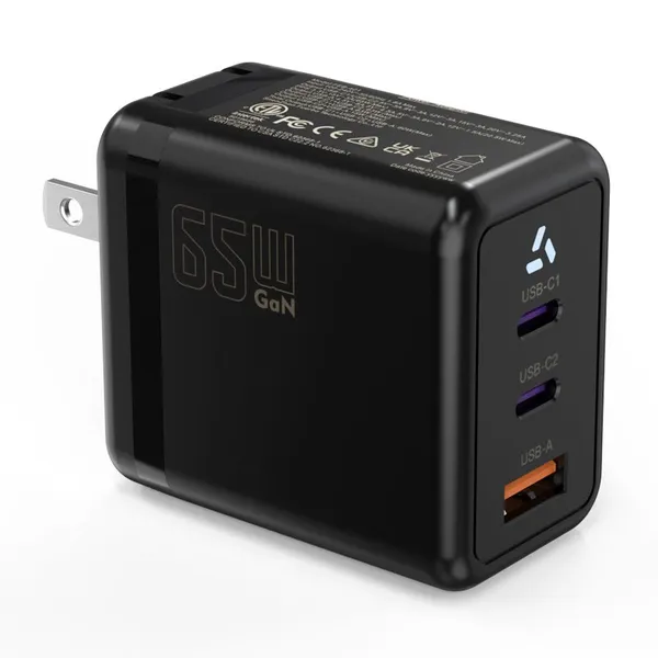
 65W USB-C GaN Wall Charger PD Fast Charging Adapter EU US Plug for Laptop Smartphone and TravelUS$ 6MOQ: 100 Pieces
 -
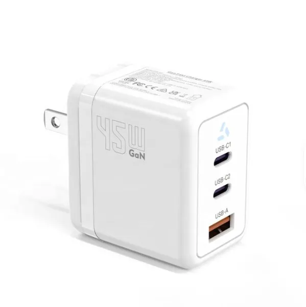
45W GaN USB-C Fast Charger JP Plug PD Wall Charging Adapter for IPhone MacBook and TabletsUS$ 8MOQ: 100 Pieces
-
QC3.0 30W USB Fast Charger With 18W Quick Charge Wall Adapter for Android and Mobile DevicesUS$ 4MOQ: 100 Pieces
-
Compact 18W Quick Charge 3.0 USB Charger 30W Fast Charging Adapter EU US Plug for TravelUS$ 2MOQ: 100 Pieces
-
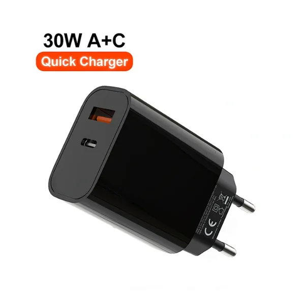
30W USB-C and USB-A PD Fast Charger Compact Wall Adapter for IPhone Samsung and IPadUS$ 3MOQ: 100 Pieces
-
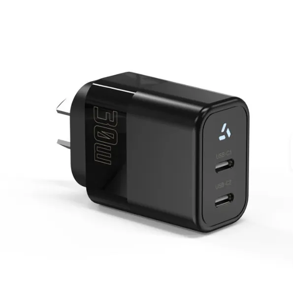
35W Dual USB-C PD Charger Fast Charging Adapter for IPhone Samsung IPad and USB-C DevicesUS$ 3MOQ: 100 Pieces
-
65W USB-C GaN Charger EU Plug Fast Charging Adapter 65W USB-C PD Fast Charge Wall Charger Power Adapter for Macbook ProUS$ 5MOQ: 100 Pieces
-
65W GaN USB-C Fast Charger PD Wall Charging Adapter for Laptop IPhone and Mobile DevicesUS$ 5MOQ: 100 Pieces
-
100W GaN USB-C Fast Charger With PD 3.0 for Laptop, MacBook, IPhone & Multi-Device ChargingUS$ 12MOQ: 100 Pieces
-
45W GaN USB-C Fast Charger EU AU PD Fast Wall Charging Adapter for IPhone Tablets With CE REACH PassedUS$ 8MOQ: 100 Pieces
-
QC3.0 65W GaN USB C Super Fast Charger With UKCA 3 Ports PD 3.0 GaN Charger for Iphone Macbook SamsungUS$ 10MOQ: 100 Pieces
-
30W USB-C and USB-A GaN QC3.0 Fast Charging Adapter PD Fast Charger Compact Wall Adapter for IPhone Samsung and IPadUS$ 3MOQ: 100 Pieces
-
45W GaN USB-C Fast Charger With Dual Type-C and USB-A Ports PD Wall Charging AdapterUS$ 8MOQ: 100 Pieces
-
Dual USB C Ports QC3.0 30W Fast Charger With EU UK AU US USB-C PD Wall Chargeer 30W PD Power AdapterUS$ 3MOQ: 100 Pieces
-
Compact 65W GaN USB-C Wall Charger With Dual USB-C Ports and USB-A Fast Charging Adapter With CE UKCA ETL SAAUS$ 10MOQ: 100 Pieces
-
QC3.0 Fast Charging Adapter PD30W USB-C USB-A GaN PD Fast Charger PD 3.0 GaN Charger Compact Wall Adapter for IPhone Samsung and IPadUS$ 3MOQ: 100 Pieces
-
12V 5A 60W US EU AC DC Adapter LED Driver LED SMPS AC to DC Switching Power SupplyUS$ 5 - 7MOQ: 50 Pieces
-
CE FCC CUL SAA KC PSE 24Vdc 48W Switching Power Supply AdaptersUS$ 5 - 7MOQ: 50 Pieces
-
CE GS UKCA SAA CUL Qualified Waterproof Switching Power Supply Ip68 PSE UL SAA GS 12V 2AUS$ 3 - 6MOQ: 50 Pieces
-
12V 1A Factory OEM Waterproof AC Adapter for Laser Light Table Lamp ac dc Adaptor With TUV CE GS for EU MarketUS$ 5 - 7MOQ: 50 Pieces